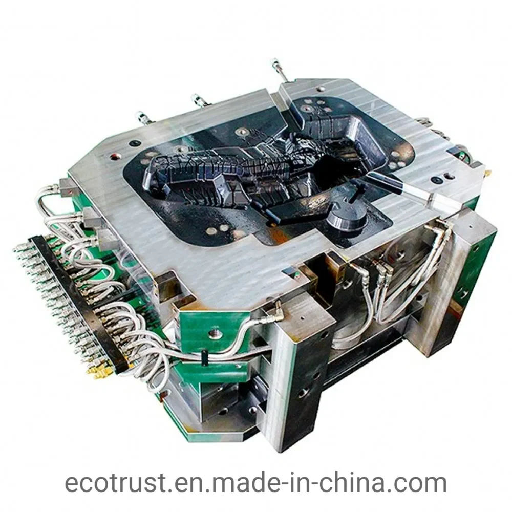
The offer covers aluminium die casting moulds and project discussion around the part and casting equipment.
Die casting mold supplier for aluminum-alloy projects
The YOMATO mould offering identifies aluminum-alloy tooling for auto parts, motorcycle parts, LED lamps and electrical-parts applications. Use these as application contexts when describing a project.
Identify whether the job is a new production tool, a change to an existing tool or a replacement insert.
An aluminium die casting mold is tooling for the part
The aluminum alloy is the material of the cast component. The die is the reusable tool that forms it. NADCA’s die-construction explanation describes alloy-tool-steel dies with stationary and ejector sections, plus features for metal entry, cooling and ejection. The part alloy and the tooling material therefore need separate specifications.
For an aluminium die casting mould project, keep the part’s material requirement attached to its drawing. Record the tool-material and treatment requirements separately in the tooling scope, rather than copying a casting-alloy designation into the die-material field.
Define the tooling scope before a quotation
When reviewing a die casting mould manufacturer, compare the proposed work as carefully as the finished tool. Different die cast mold manufacturers may quote different deliverables against the same component drawing.
- Part definition: drawing and revision, alloy, critical dimensions, surface requirements and machining allowances.
- Production context: intended casting equipment, component demand and any existing tool-interface constraints.
- Purchased scope: required design work, tool supply, trial parts, inspection information and delivery condition.
- Acceptance: what will be reviewed, who approves it and how design changes are recorded.
Treat a request for trial parts, inspection records or tool-maintenance work as a scope item to define, rather than assuming every item accompanies every tooling order.
Review part features that affect a die-casting tool
Release geometry deserves attention early. NADCA’s draft guidance explains that the taper needed for ejection varies with the surface, its depth and the alloy. A feature that looks simple in a drawing may still need a release-direction discussion.
Wall transitions are another review point. NADCA’s uniform-wall guidance favors consistent walls where practical and transitions where thickness changes are required. The useful question is how the actual part geometry will be handled, rather than asking for one universal minimum wall value.
Tooling photographs and related equipment
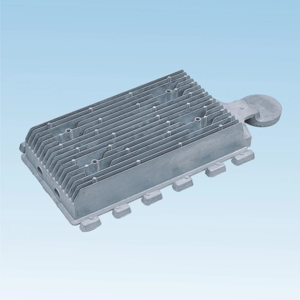
The representative mould tooling photograph shows a central cavity, metal plates and external pipework. The finned cast-part image is a separate example of component geometry.
Review the cold-chamber die casting machine context alongside the tool interface. For background on the process families, read hot chamber vs cold chamber die casting.
Send the project brief to sales@hotchamberdiecasting.com.
Questions and answers
Does an aluminum die cast mold use aluminum for the die?
The name commonly refers to the aluminum part being cast. NADCA describes the die itself as alloy tool steel. Keep those material specifications separate when reviewing the tooling scope.
What should I include in a tooling RFQ?
Attach one drawing revision, identify the intended machine and state the component demand. Mark critical dimensions and finish requirements so the reviewer can find them without comparing conflicting versions.
Are tool steel, trial casting and inspection included?
Tool supply, trial castings and inspection records are separate deliverables. For each requested item, identify the delivery form and acceptance reviewer.
How should mold life or lead time be compared?
Compare the stated conditions and milestones, including the part, alloy, production assumptions and acceptance requirements. A single life or delivery figure is less useful when the underlying scope differs between quotations.