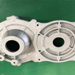
Abstract: The gating system plays an important role in controlling the flow direction and state of the molten metal in the mold, exhaust overflow conditions, pressure transmission of the die-casting mold, etc., and can adjust the filling speed, filling time, and temperature distribution of the die-casting mold, etc. https://www.ptjmachining.com/The process conditions for filling the cavity. Therefore, the design of the gating system is an important factor that determines the quality of die castings, and it also has a great impact on production efficiency and mold life. The design of the pouring system must be systematically considered, according to the classic fluid filling theory combined with the product structure layout of pouring and overflow.
1. Design of the position of the inner gate
In the design of the gating system, the design of the inner gate is extremely important. Before determining the position of the inner gate, it is necessary to fully predict the position of the selected inner gate according to the basic situation of the die casting cavity and the different types of parting surfaces. The influence of the flow state of the molten metal when filling the cavity, the analysis of the dead angle and the entrapped part that may occur during the filling process, so as to arrange the appropriate overflow and exhaust system. The following principles should be followed:
(1) The introduced molten metal should first fill the deep part of the cavity that is difficult to vent, and it is not appropriate to immediately seal the parting surface to cause poor venting.
(2) The molten metal flowing into the cavity should be minimized to reduce twists and turns, avoid excessive eddy currents, and reduce entrapment gas.
(3) Generally set at the thick wall of the die-casting part, which is conducive to the pressure transmission of the feeding flow after the molten metal fills the cavity.
(4) Consideration should be given to reducing the diversion of molten metal in the cavity to prevent the diversion of molten metal from causing cold joint marks or cold separation at the junction.https://www.wondercopper.com/
(5) Avoid direct impact of molten metal on the core, reduce kinetic energy loss, prevent erosion and mold sticking, and especially avoid impact on small cores or threaded cores to prevent bending and deformation.
(6) Inner gates should not be arranged for parts with high accuracy requirements, low surface roughness values and unprocessed parts to prevent marks from being left after the gate is removed.
(7) The setting of the inner gate should consider the distribution of the mold temperature field, so that the distal end of the cavity can be filled well.https://tsmachining.com/
(8) The removal method of the gating system should also be considered.
2. Calculation of the cross-sectional area of the gate
The inner gate is generally the part with the smallest cross-sectional area and the largest resistance in the gating system. The product of its cross-sectional area and the flow velocity of the molten metal there is equal to the product of the cross-sectional area of the pressure chamber and the flow velocity of the molten metal in the pressure chamber, and It is equal to the ratio of the volume of molten metal flowing through the pressure chamber (the sum of the volume of the cavity and the overflow tank) and the elapsed time.
3. Horizontal gate design
The runner is a passage between the molten metal flowing from the end of the sprue to the inner gate, and its function is to introduce the molten metal into the inner gate, and at the same time, it is used to feed and transmit static pressure when the die casting is cooled.
Key points of horizontal gate design:
(1) The cross-sectional area should be gradually reduced from the end of the sprue to the gate stop. Otherwise, the cross-sectional area of the runner will expand, which will cause negative pressure in the molten metal flowing there, which will inevitably absorb The air on the parting surface increases the vortex during the flow of the molten metal.
(2) The cross-sectional area of the primary runner of the multi-cavity die-casting mold should be greater than the sum of the cross-sectional areas of the secondary runners.
(3) The cross-sectional area of the runner should be greater than the cross-sectional area of the inner gate in any case.https://sandcasting.org/
(4) In order to reduce the metal flow resistance and achieve a balanced flow rate, the runner should not shrink and expand suddenly.
(5) In order to improve the thermal balance conditions of the mold, blind runners can be set according to process requirements. At the same time, blind runners have the function of holding cold contaminated metal and gas.
4. Design of overflow tank
The role of overflow tank:
(1) It contains the cold dirty molten metal that first enters the cavity and the gas and oxidation inclusions mixed into it to prevent cold barriers, pores and slag inclusions in the die casting.
(2) When the pouring system is selected, the setting of the overflow groove can control the flow state of the molten metal together with the pouring system, prevent local eddy currents, and create filling conditions that are beneficial to avoiding die casting defects. Sometimes it is also used to transfer shrinkage cavities, shrinkage porosity, vortex air entrapment and cold joint marks.https://lasercutting-service.com
(3) Adjust the temperature distribution of the mold to improve the thermal balance of the mold, especially for thin-walled or long-filled die-casting parts, which can reduce the surface flow marks, cold separation and insufficient filling of the die-casting parts.
(4) In some cases, the overflow groove can be used as the position where the push rod is pushed out when the die-casting part is demolded, to prevent the die-casting part from deforming and avoid leaving traces of the push rod on the surface of the die-casting part.
(5) In order to prevent the die-casting parts from staying in the fixed mold when the clamping force of the die-casting parts against the moving and fixed mold parts is nearly equal, an overflow groove can be set on the movable mold at this time to increase the pressure of the die-casting parts against the movable mold. The tight force ensures that the die-casting part stays in the movable mold during parting, which is convenient for the ejection and demolding of the ejection mechanism.https://cncmachining.jp
(6) For vacuum die casting and directional pumping pressure casting, the overflow groove is often used as the starting point for gas extraction.
Location selection of overflow tank
The selection of the location of the overflow tank should follow the following principles:
(1) The overflow tank should be opened at the position where the molten metal first impacts to remove the gas and cold dirty molten metal at the front of the molten metal flow, stabilize the flow state, and reduce eddy currents.
(2) The overflow tank should be opened at the place where the two molten metal streams meet to remove the concentrated gas, cold dirty molten metal and paint residues.
(3) The overflow groove should be opened on both sides of the inner gate or the dead corner area where the molten metal cannot be filled smoothly to play the role of drainage and filling.https://ptjcnc.com
(4) The overflow groove should be opened in the local thickness of the die casting, and its capacity and the thickness of the overflow should be increased, so as to transfer the gas, slag and shrinkage to this place, and improve the thickness of the die casting. quality.
(5) The overflow tank should be opened in the place where the molten metal is filled at the latest to improve the thermal balance of the mold and the filling and exhaust conditions.
(6) When designing the overflow groove, it should also be noted that the appearance of the die casting cannot be affected or damaged after the overflow groove is removed.
(7) Several overflow ports should not be opened on the same overflow groove, so as to prevent the metal flow from flowing back to the cavity from the overflow groove and causing backflow.https://numerical-control.com/
5. The cross-sectional size of the exhaust groove
At present, the domestic die-casting industry is developing rapidly, but the design and development cycle is very short. The mold designers are mostly mold technicians. The design scheme lacks systematic analysis and proofreading calculations. Therefore, there are often multiple trials in the subsequent die-casting production. The mold is unqualified, or the product qualification rate is low, the production efficiency is low, and the mold life is short. Based on the classic fluid filling theory, the characteristics of aluminum alloy materials and the actual situation of die-casting production, this article summarizes and solidifies the relevant precautions and calculation formulas for mold pouring and overflow, for reference by industry peers.


